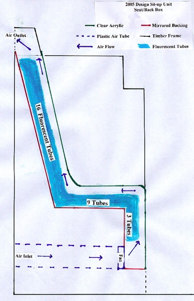
View of the seat/back box before installing tubes and acrylic cover.
The major structural material is 12 mm (half inch) pineboard. 24 mm X 20 mm pine cleats are used as supports and joins.
|
|
PHOTOGRAPHS AND SKETCHES
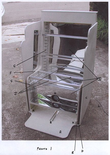
PHOTO 1
View of the seat/back box before
installing tubes and acrylic cover.
The major structural material is 12 mm (half inch) pineboard.
24 mm X 20 mm pine cleats are used as supports and joins.
A.
Base sits on carpet
B. Guide for wheel of front box made from aluminium angle.
C. Outer frame
D. 24 mm gap for front box to fit into
E. Inner frame
F. Spacer made of two layers of 12 mm board to create gap
referred to at D
G. Tube holders 16 in sloping back part, 9 in horizontal
seat part and 3 on vertical section behind calves.
H. Inlet fan. Sucking air from behind the box via a plastic
tube and blowing through light space and out at the rear of the
top of the back box. Note that what appears to be another fan
on the horizontal floor is really a reflection of the fan on the
vertical section.
I. Back of light space. Made of board and covered with
2 mm acrylic mirror. The light space (about 90 mm wide) is created
between these surfaces and the clear acrylic shield (not fitted
in this photo). Wiring from tube holders goes through small holes
in this board/mirror to the ballasts at rear.
J. Supports for clear acrylic made of 25 mm aluminium angle.
Note the angle is fitted into tight slots cut in inner frame.
They cannot come loose because the clear acrylic shield is fitted
over them to the inner frame edge.
K. Cleats holding vertical part of inner frame to floor.
L. Power lead.
PHOTO 2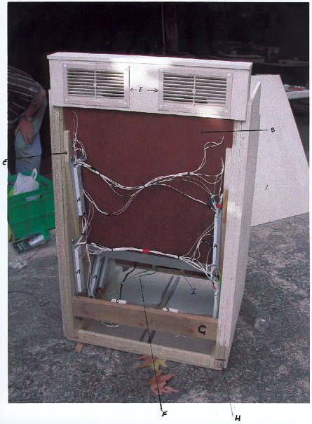
Rear view of seat/back without
the thin plywood back cover. Note a 150 mm plastic pipe (not shown)
is fitted from the fan and through a 150 mm hole in the back cover
so that the fan is sucking air from the room and not just from
the bottom of the light box.
A.
Electronic ballasts each for 4 tubes. Ballasts are in this area
and not in light space because of space and possibly heat load
considerations.
B. Back of board creating the light space.
C. Supports for board creating light space
D. Junction boxes for power distribution to ballasts and
fan.
E. Air outlets from light space
F. Wiring to fan
G. Structural support
H. 12 mm inner frame, 2 X 12 mm spacer, 12 mm outer frame
I. Fan inlet
PHOTO 3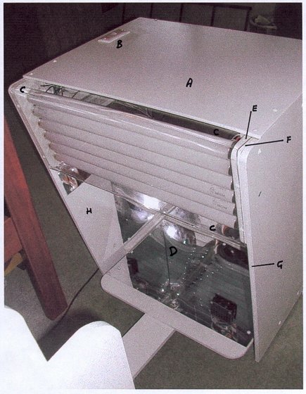
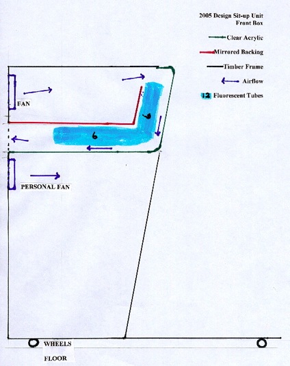
Front box with acrylic shield
fitted over tubes
A.
Table top
B. Switch for personal fan
C. Acrylic shield with short horizontal section fitted
just under the table so that light can shine in an upward direction
(Albeit under the overall cloth cover (not shown). It then has
a vertical section (actually slightly sloping) before a long horizontal
section over the 6 tubes (not shown except as an image in the
floor mirror) above the users thighs. Note because of the short
span and because there is no weight or pressure on the front box
acrylic it was not necessary to use aluminium supports.
D. Below the light space the surfaces are fitted with mirror
except where the front box fits into and overlaps the seat/back
box. When in use the users feet are on this floor because it sits
above the floor of the seat/back box.
E. Inner frame.
F. Spacer to allow the front box to fit between the inner
and outer frame of the seat/back box.
G. Outer frame
H. Area of frame where no mirror is fitted because when
in use this part is between the inner and outer frame of the seat.
PHOTO 4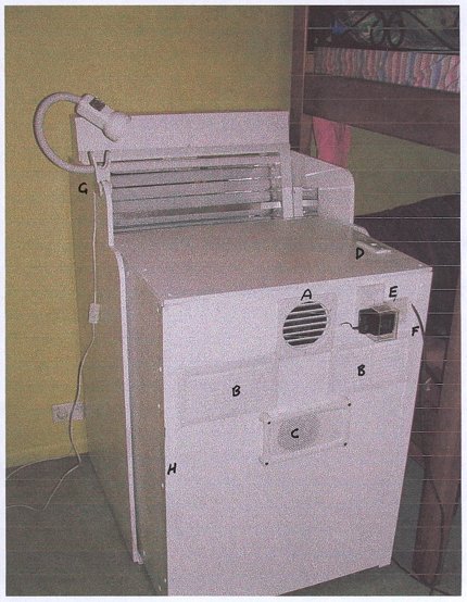
Front and back fitted together and showing
detail of outside of front box. Note that the cloth cover is fixed
by Velcro to the top of the back and to the top of the outer frame
of the seat and lays a short distance onto the table, but allowing
the light to shine upwards.
A. Fan cover. Fan is inside and air is being sucked through
this cover.
B. Air outlets. There is an internal baffle that allows
air to be blown downwards across the vertical tubes, then across
the horizontal tubes and out the vents marked B.
C. Direct current Personal fan (inside) sucking room air
and blowing over the user. Note that there must be an adequate
guard on this fan on the inside because it si not far from the
users knees.
D. Switch for personal fan. (DC)
E. Fan speed controller that operates by changing the voltage
F. Power lead.
G. The light clipped to the seat is not part of the unit
and is used only for reading.
H. Aluminium angle used on outside edge of front box for
strength.
SKETCHES
A sketch of each box showing internals and air flows.
Note dimensions are not shown because they may be different for different users. Laurens lights are built for someone who is 5Ft plus or minus about 3 inches (1500 mm+/-75 mm).
Sketches are fairly close to scale and originally were one fifth scale. The total height of the seat/back box is 1220 mm above the floor and the width (excluding the floor extension is 600 mm). The height of the front box is 940 mm above the floor using wheels that keep the base 30 mm above the floor.
Copyright 2006.